Introduction.
This guide will explain how to create and edit your first network diagram. I'll assume you already have an account created.
Creating and Sharing.
Right after you log into NetworkMaps, you will see a screen showing you a list of your network diagrams (provided that you already have created network diagrams).
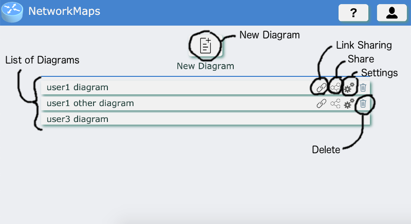
Here you can do the following
- New Diagram. Create a new diagram. Once clicked on this option, you will be asked for the name of the new network diagram.
- List of Diagrams. List of all the diagrams you have access to. Either because you created them (then you are the owner) or because someone shared them with you (in which case you'll have either read only or read write access). To access the diagram, click on the name of it. If you are the owner of the diagram, you'll see on the diagram a set of buttons:
- Link Sharing. Use this option if you want to share this diagram with anyone who has the link to the diagram. The diagram will be reachable by anyone with the link as Read Only. It will show a window where you can configure this setting as well as get the link to the diagram.
- Share. This option will allow you to share the diagram with specific people. It will open a window where you can specify the email address of the person you want it to be shared with and what permissions you want to give him on this network diagram.
- Settings. It will open a window where you will be able to rename the diagram and manage the list of users it is shared with.
Once you have created your first network diagram, click on it and you will be able to edit it.
L2/L3 Diagram - Steps.
To create a proper network diagram where you document all L2 and L3 properties of your network, you can follow these steps. We will detail them in further sections.
Edit the L2 Diagram.- Add the physical devices of your diagram.
- Add the physical links between devices.
- Add additional passive items (bases, texts, symbols, ...).
- Configure device names and adjust visual aspect of devices.
Configure L2 Elements.- Configure the devices:
- Loopback Interfaces.
- VLANs.
- VRFs.
- Configure device links.
- Transceivers, interface names, aggregated Interfaces.
- L3 Interfaces and subinterfaces
- L2 Interfaces (access ports and trunks).
- L3 interface.
Edit & Configure the L3 Diagram.- Adjust position of elements on L3 diagram. As you progress on configuring the devices and device links, the L3 diagram will automatically be created. But NetworkMaps doesn't know where to place the different elements. So it will place them in random positions. You'll need to adjust the position of each element.
- Add additional passive items (bases, texts, symbols, ...).
- Configure IP addressing.
L2 Diagram - Elements.
A L2 Network Diagram is made up of different elements:
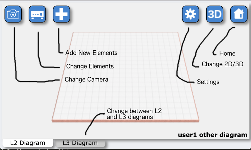
- Camera.The camera defines the place from where you are looking to the diagram. It is you on the 3D space. You can move the camera with the Change Camera button:
- Move (quick access key 'q'). Once selected this option, press the mouse button anywhere in the diagram and move the mouse.
- Rotate (quick access key 'w'). Once selected this option, press the mouse button anywhere in the diagram and move the mouse.
- Zoom (quick access key 'e'). Once selected this option, press the mouse button anywhere in the diagram and move the mouse.
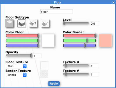 Bases.Bases are basically the "floors" of your diagram. You place the rest of the elements on top of bases. Currently we support only Floors as bases. A Floor can have the following properties:
- Floor Subtype. Defines th aspect of the floor.
- Level. Height of the floor.
- Color Floor. Color of the floor.
- Color Border. Color of the border and the "legs" of the floor.
- Opacity. How opaque the floor is. This is a number between 0 and 1 where 0 is fully transparent and 1 is fully opaque.
- Floor Texture. Image "printed" on the floor.
- Border Texture. Image "printed" on the border.
- Texture U & Texture V. UV coordinate rates used when drawing the texture on the floor. Defines how "big" the texture is.
 Devices.Devices is the most basic element of a network diagram. It represents each one of the physical elements that compose your network. They can be routers, switches, servers or any other element that is connected to the network. Devices can have different shapes based on your preferences. To add new devices into your network, first click on the "Add Element" button, then select "Device" on the menu, and choose the shape this new device will have. Finally, click on the base where you want this device to be. A device will always be on top of a base element.
Devices have different settings:
Devices.Devices is the most basic element of a network diagram. It represents each one of the physical elements that compose your network. They can be routers, switches, servers or any other element that is connected to the network. Devices can have different shapes based on your preferences. To add new devices into your network, first click on the "Add Element" button, then select "Device" on the menu, and choose the shape this new device will have. Finally, click on the base where you want this device to be. A device will always be on top of a base element.
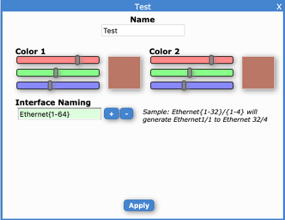
Devices have different settings:- Name. Name of this device. The device name will appear on top of each device. You can hide the name of the devices on the general settings.
- Color 1 and 2. Devices have two colors. The first one is usually for the simbol and the second one for the "border" (this depends on the device shape).
- Interface Naming. This is a list of expresions to generate the possible interface names for this device. The interface names will be used later to configure the device and device links.
 Links.Links represent the physical cables that connect the different network devices and servers. A link can be a single cable or a set of cables forming a port channel. To add links:
- Select the "Add New Elements" button.
- Select "Links".
- Select "Line" or "Squared" depending if you want the link to follow a straight line between the connected devices or it to be bent on the axis.
- Click on the source devices and while holding the mouse button, move the mouse to the destination device.
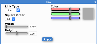
Links have different settings:- Link Type. As described before, whether the link follows a straight line between devices or not.
- Square Order. For squared links, the order in which the link is bent to destination (order in which axis are applied).
- Width. Defines how thick is the link.
- Height. Position of the link in the Y axis.
- Color. This is probably self explanatory.
- Link Bends.Only in "Line" links, we have the option of adding custom defined bends on these links. For this:
- Select the "Add New Elements" button.
- Select "Links".
- Select "Bend".
- Click on the link where we want to add a bend.
- Select the move tool ("Change Elements" => "Move").
- Click on the link where we added the bend and while holding the mouse button, move the bend to the desider position.
- Symbols.Symbols are elements on the diagram that have no active part on it. They are there just to add some information to people. These can be flags, arrows or other simbols.
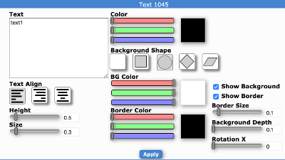 Text.As symbols, text are passive and informational elements on the network diagrams. They have a set of settings to change their aspect:
- Text. The text that will appear.
- Text Align. Alignment of the different lines that form the text. Left, center or Right.
- Height. Position of the Y axis of the text relative to the base it belongs to.
- Size. Size of the text.
- Color. Color of the text.
- BG Color. Color of the background.
- Border Color. Color of the border of the text.
- Background Shape. Shape of the background and the border of the text (if shown).
- Show Backhround.
- Show Border.
- Border Size.
- Background Text.
- Rotation X. Rotation of the text relative to the background.
Edit the L2 Diagram.
First step to create a network diagram will be to add and position the different elements that form this diagram.
Add new Devices.- Click on the "Add New Elements" toolbox.
- Select "Devices" on the toolbox that appears.
- Select the shape of the device we want to add.
- Click on the base where we want this device to appear.
Add new links.- Select the "Add New Elements" button.
- Select "Links".
- Select "Line" or "Squared" depending if you want the link to follow a straight line between the connected devices or it to be bent on the axis.
- Click on the source devices and while holding the mouse button, move the mouse to the destination device.
Add text.- Select the "Add New Elements" button.
- Select "Text".
- Click on the base where we want this text to appear.
- As soon as we click on the place where we want text to appear, the text settings window will appear. Here we can configure the aspect of this text as well as the text that we want.
Add symbols (Arrows, Flags, ...).- Select the "Add New Elements" button.
- Select "Symbol".
- Select the type of symbol you want to add (arrows, flags, ...).
- Click on the base where we want this symbol to appear.
- Each type of symbol has different settings that define their look and feel. To change the appearance of a symbol, open the settings window of that element.
Modifying Elements of a Network Diagram.
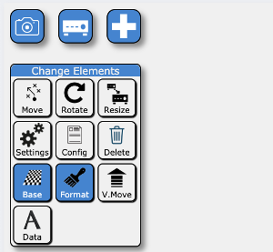
Once you click on the "Change Elements" toolbox, a new box will appear with the different actions you can do on the diagram elements. These are:
- Move (quick access key 'a'): move elements horizontally. Once selected this tool, drag and drop the different elements of the diagram. It's possible to select multiple elements and move them together. To do this, hold Shift while clicking the elements and move one of them while holding Shift.
- Rotate ('s'): rotate elements on the Y axis.
- Resize ('d'): resize elements evenly so they keep the same aspect ratio.
- Settings ('z'): open the settings window of elements. Once selected this tool, click on the element whose settings you want to open.
- Config ('x'): open the config window of elements. Configuration will be explained on a further section.
- Delete ('c'): remove elements from the diagram.
- Base: open the base toolbox. This toolbox has similar options as the current one but applyed to bases. We have a different toolbox for changing bases to avoid changing the bases while editing the diagram.
- Format: open the toolbox to copy/paste formats and default formats applied to new elements.
- V. Move: Vertically move elements.
- Data: Change the data displayed on mouse over for the different elements of the network diagram. By default, a summary of the configuration is shown on mouse over. If you want this to be changed, this is where you configure it.
- URLs: This option let's you assign URLs to any element of a diagram. These urls will then be accessible on the infobox of an element or by rightclicking it.
- Shapes: A diagram has several Shape Groups assigned. A shape is each type of element you can add to your diagram. With this option you can define which shape groups are available on this diagram.
Configure L2 Elements.
NetworkMaps is capable of automatically generate a L3 Network Diagram based on your L2 diagram. For this to work properly, you need to define how the different devices and links are configured: what vlans and vrfs each device has, what links are L2 or L3 and how are they tagged, ... . This is done using the "Config" tool.
Configuring Devices.
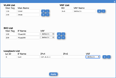
Once opened the configuration window of a device, we will be able to configure vlans, vrfs, SVIs, ... on this device. This information will be used to autogenerate the vrfs and vlans on the l3 diagram and connect them together using the svi information:
- Vlan List: list of vlans that exist on this device. Each vlan will be generated on the L3 diagram.
- Vlan Tag: VLAN ID of this vlan.
- Vlan Name: A name assigned to this vlan for informational purposes.
- Vrf List: list of VRFs that exist on this device. All devices come with a predefined VRF: the default VRF.
- RD: Route Distinguiser of this VRF. Should be unique per VRF within this device.
- VRF Name: A name assigned to this VRF for informational purposes.
- SVI List: List of SVIs (Switch Virtual Interfaces) on this device). SVIs are the device internal connections between VRFs and VLANs.
- Vlan Tag: vlan tag of the vlan this SVI is connected to. It should exist on the VLAN list.
- If Name: name of the interface.
- VRF: name of the VRF this SVI belongs to
- Loopback List: List of loopback interfaces.
Configuring Links. Physical Properties.
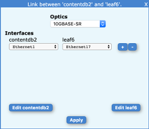
Links connect 2 devices. As such, when we configure a link, we will have to configure both sides.
When we open the Link Config window, we will initially see the physical configuration of a link. This is what type of connection it is (transceivers used), and the physical interfaces used on both sides.
- Optics: Let's you define what type of transceivers are used for this connection. As transceivers have to match on both sides, you only have to define it once and will apply to both devices.
- Interfaces: List of physical interfaces on both sides of this link. Interface names are derived from the interface naming defined on each device settings. If you define more than one interface per device, a truck will be assumed and you can configure if LACP is used or not.
Also on this window, we will have a button per side of the link where we can open the window to edit L2/L3 settings of these links. When clicked, a new window will appear where we can configure the link type (None, L2 or L3) as well as the properties specific to this link type. These will be explained on the next sections.
Configuring Links. L2 (switchport) Interfaces.
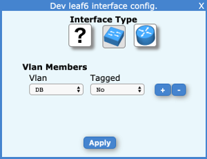
L2 Interfaces are interfaces where our devices only switches traffic (withing a defined vlan). This is the most common type of interfaces on switches. For these type of interfaces, we have the following settings:
- Vlan Members: List of vlans on which this port can receive traffic. Note that this is a list and can have more than one vlan per interface. But only one vlan can be defined as native.
- Vlan: Vlan name. Must be defined on the device config itself.
- Tagged: Whether the device expects traffic on this vlan to be tagged or not. Only one vlan on the list can be untagged.
Configuring Links. L3 (routing) Interfaces.
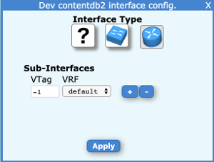
L3 interfaces are interfaces used for routing traffic. These interfaces are the most common type of interfaces on routers or servers and usually will have IP addressing assigned (IP addresses are defined on L3 network diagrams).
- Sub-Interfaces: although not used widely, a physical L3 interface can have more than one subinterface. Although the most common case is just having one. If used more than one sub-interface, these will need to be tagged so the other side understand to which subinterface the traffic belongs.
- Tag: vlan tag used on this interface (this tag is completely independant of the vlans defined on the device). If untaged, mark with -1.
- VRF: VRF this interface belongs to.
Edit & Configure the L3 Diagram.
Once a L2 diagram is created and the devices and links on it have been configured properly, the different components of a L3 network diagram are automatically generated. This automation process doesn't try to place these components in a nice way, so the first task to be done will be to arrange them on a logical way. Second part will be to configure IP addressing of these elements.
Before moving on how to configure IP on these elements, let's look at what elements form a L3 network diagram:
- VRFs: Each time you configure a VRF in a device, this VRF will be automatically created on the L3 diagram. A VRF is a logical router.
- L2 Segments: a L2 Segment is the equivalent of a VLAN on L2 diagram. When you configure a VLAN on a device, a L2 Segment will be created on the L3 network diagram.
- L2 Link: A Layer 2 link represents the connection between two VLANs on different devices. A L2 Link is generated when a link has both sides configured as L2 interfaces and there will be a L2 link per vlan on the vlan list that matches on both sides.
- P2P Interfaces: a Point to Point interface represents the direct connection between two VRFs. A p2p interface is generated when a link has both sides configured as L3 interfaces and both have a subinterface with the same vlan tag.
- Interface: an interface represents the connection between one VRF and a L2 Segment (VLAN). They are generated when one side of a link is configured as L2 and the other is configured as L3 (like how servers are connected to switches) and the vlan tag of an interface matches a vlan id on the other (or when both are configured as untagged).
- SVI Interfaces: an SVI interface is the virtual interface connecting a VRF in a switch to a VLAN on himself. These interfaces are created when you configure them on a Device.
- Bases, Text and Symbols: as on L2 diagrams, text and symbols are elements added for informational purposes and don't really participate on the logic of the network diagram.
 Here you can do the following
 Bases.Bases are basically the "floors" of your diagram. You place the rest of the elements on top of bases. Currently we support only Floors as bases. A Floor can have the following properties:
 Devices.Devices is the most basic element of a network diagram. It represents each one of the physical elements that compose your network. They can be routers, switches, servers or any other element that is connected to the network. Devices can have different shapes based on your preferences. To add new devices into your network, first click on the "Add Element" button, then select "Device" on the menu, and choose the shape this new device will have. Finally, click on the base where you want this device to be. A device will always be on top of a base element.
Devices have different settings:
 Links.Links represent the physical cables that connect the different network devices and servers. A link can be a single cable or a set of cables forming a port channel. To add links:
 Text.As symbols, text are passive and informational elements on the network diagrams. They have a set of settings to change their aspect:
 Once you click on the "Change Elements" toolbox, a new box will appear with the different actions you can do on the diagram elements. These are:
 Once opened the configuration window of a device, we will be able to configure vlans, vrfs, SVIs, ... on this device. This information will be used to autogenerate the vrfs and vlans on the l3 diagram and connect them together using the svi information:
 Links connect 2 devices. As such, when we configure a link, we will have to configure both sides.
 L2 Interfaces are interfaces where our devices only switches traffic (withing a defined vlan). This is the most common type of interfaces on switches. For these type of interfaces, we have the following settings:
 L3 interfaces are interfaces used for routing traffic. These interfaces are the most common type of interfaces on routers or servers and usually will have IP addressing assigned (IP addresses are defined on L3 network diagrams).